This started as the MCTE5255 Mechatronics Engineering Design project — a four-person
team building a controller for a provided soft robotic rehabilitation glove. I led the
detailed control-system design. After the course, I was recruited as a Research
Assistant in the College of Engineering to take the controller further under a funded
grant on soft robotic actuators for tele-rehabilitation.
The project scope was the controller rather than the glove hardware: actuator sequencing,
sensor feedback, safety limits, and repeatable bench tests.
Problem
Pneumatic soft actuators are nonlinear; open-loop timing can't be trusted.
Air is compressible and the glove’s pressure-to-motion response has delay and hysteresis,
so a fixed inflation time does not give a repeatable finger posture. The controller has to
close the loop on finger bending, sequence inflation and vacuum-assisted extension
without ever fighting itself, and stay inside hard safety limits — all on a compact,
battery-powered, well-documented platform.
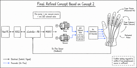
A centralized ESP32 coordinates sensing, control, actuation, and telemetry. Low-power
logic is electrically isolated from the higher-current pneumatic loads.
Subsystem
Component
Role
Controller
ESP32 (LOLin D32)
FSM, PID, 12-bit ADC, telemetry
Pressure
12 V diaphragm pump
Inflation / flexion
Vacuum
6 V mini pump (370A)
Active extension
Driver
Cytron MDD10A
20 kHz PWM pump drive
Routing
3/2 solenoid valve + 1-ch relay
Pressure ↔ vacuum switching
Feedback
4.5" flex sensor
Finger-bend estimate (ADC)
The whole control unit comes in under 750 g and within the 50 OMR budget
(~41 OMR of commercial parts).
Final control architecture — one pump, one vacuum source, and a single 3/2 solenoid valve, with flex-sensor feedback closing the loop.
Control Logic
A four-state machine with closed-loop inflation and hysteresis-held extension.
Firmware (C++ / Arduino-ESP32) runs a ~50 Hz loop with 5-sample sensor averaging and a
four-state cycle:
INFLATING — unidirectional PID (Kp 4.0 · Ki 0.1 · Kd 1.5) drives the pressure
pump toward the flexion target (≈ 2800 ADC), with anti-windup and a deadband so it
doesn’t hum near setpoint.
HOLD_FLEX — a low maintenance PWM counters slow leakage to hold the posture.
VACUUMING — pressure off, vacuum on to return toward the open hand (≈ 1850 ADC).
HOLD_VAC — bang-bang hysteresis (±100 ADC) keeps the hand open.
A safety watchdog cuts pump power immediately on overshoot or above an ADC ceiling of
3500, and the state machine structurally prevents pressure and vacuum from ever driving
against each other.
Bench Results
The full rehabilitation cycle ran repeatably under instrumentation.
Tests were run on the physical prototype in the SQU Mechatronics lab and streamed over
serial telemetry (sensor · state · PWM · relay) at 115200 baud.
Test
Target
Result
Flex-sensor calibration
ADC ≈ 1850 / 2800
Met
PID inflation
Smooth rise, no overshoot
Met
Vacuum extension
Returns to open-hand target
Met
Full cycle ×3
Consistent completion
Met
Safety cutoff
PWM → 0 at ADC ≥ 3500
Met
Budget & mass
≤ 50 OMR, < 750 g
Met
Evolution
From one bench rig to a documented five-finger controller.
Work continued past the course build into a cleaner, fully five-finger bench line,
kept deliberately simple so it can be demonstrated and validated end to end. A single
central 3/2 valve selects pressure or vacuum for the whole manifold, and each finger
gets a normally-open 2/2 isolation valve: as a finger reaches its target angle its
valve closes and holds, while pressure keeps driving the fingers that haven’t arrived yet.
With a shared pneumatic line, the fingers inflate or extend together, while individual
valves isolate each finger at its target angle. The system does not provide
independent pressure control for each finger.
Line
Board
Control
Telemetry
Minimal bench baseline
Arduino Mega 2560
Proportional, average-angle
USB-serial CSV + 16×2 I²C LCD + optional MPU6050
Research line
ESP32 / ESP32-S3
Feature-rich
Wi-Fi, dashboard, logging, safety architecture
The proportional baseline runs a pressure → hold → vacuum cycle on the five-finger
average, streaming a structured CSV (target, per-finger angles, error, mode, pump PWM,
valve states, and IMU) for repeatable bench logging. It is backed by a public
engineering-docs set — architecture, control strategy, calibration worksheet, pin map, and
a safety-and-validation checklist — in the
public portfolio repository.
Host-Side Tooling
Serial logging, schema validation, and step-response analysis.
Host-side tools capture, validate, and analyse controller telemetry:
Serial logger / console — records the CSV telemetry stream to timestamped files while
letting the operator issue motion, gain, and calibration commands in the same session, so
logging and tuning happen together (and the IDE’s serial monitor doesn’t fight the script
for the port).
CSV-schema validator — treats the firmware as the single source of truth for the
telemetry schema and checks every captured log against it: column count and order,
per-column types and ranges, and session boundaries. It is read-only, dependency-free, and
ships with a self-test — so report numbers are never computed on a malformed log.
Step-response analysis — segments a log at each target change and computes per-finger
and average metrics (rise time, overshoot, settling time, steady-state error), ships with
its own self-test, and is explicit that a simulation log and a bench log are different
levels of evidence — the valve-state channels stay the ground truth for actual isolation
timing.
Plotting — turns a raw log into a time-aligned, multi-panel figure: finger angles vs.
target, control error with the deadband, pump command shaded by control mode, the valve
timeline, and IMU — with separate logging sessions detected and split automatically.
The discipline underneath is the same one the controller follows: the tools are
dependency-light and self-tested, and the firmware — not a convenient assumption — defines the
schema everything else is checked against.
Simulation & Demo
A firmware-faithful five-finger simulator, in MATLAB and Python.
To develop and demonstrate the controller away from the bench, I built a real-time
five-finger simulator — a MATLAB app with a matching Python twin — whose control half
is a faithful port of the firmware’s control routine: the same average-angle proportional law,
the same deadband and minimum-PWM floor, the same pressure → hold → vacuum logic, and the same
per-finger isolation as each finger reaches its target. The pneumatic plant is clearly
labelled as a semi-empirical illustration, never as hardware proof.
It exposes live tuning of the proportional gains and of the plant’s fidelity (flow
restriction, pump dead-zone, leakage, viscoelastic creep), so the shared-air system’s
behaviour is something you can see rather than take on faith. A headless self-test backs
that up: it sweeps the gain across its full range and checks that the loss-modelled controller
never overshoots — matching the bench hardware. A separate
interactive React dashboard presents the wider design study.
Research Extension
What the Research Assistant phase adds.
The funded work extends the validated controller toward:
ROS 2 / micro-ROS integration for motion-pattern adjustment and real-time logging.
EMG intention detection (as a supervisory enable) and IMU posture sensing.
Per-finger completion logic with individual targets, and an ADC-to-joint-angle calibration curve.
Hardware safety — physical emergency stop and pressure-relief — required before any
human-subject testing.
Limitations
Honest boundaries.
This is a research and bench-validation platform — not a clinically approved device,
not patient-ready, and not human-tested. In the course phase, EMG intention detection,
full five-finger control, and ROS 2 were scoped as future work rather than delivered.
The value here is a working, documented controller and the test data that backs it up.